Hey there, I'm Thad

  • Portfolio Home
  • Engineering Projects
    • Crosswind Kite Power: Kite Control Unit
    • Gettin' Loaded: Assistive Trunk Loading
    • FDM Printer Upgrade
    • 8 Bit ALU
  • MATLAB Modeling Projects
    • Fan Cooling Modeling
    • Cruise Control Modeling
  • IT/Home Lab Projects
    • Self Hosted Modded Minecraft Server
    • Personal VPN service
    • Isolated Monitoring Tool
    • Self Hosted Cloud Storage and Music Streaming
  • Resume

Gettin' Loaded: Assistive Trunk Loading

Lead Screw and Guide Rail System Design
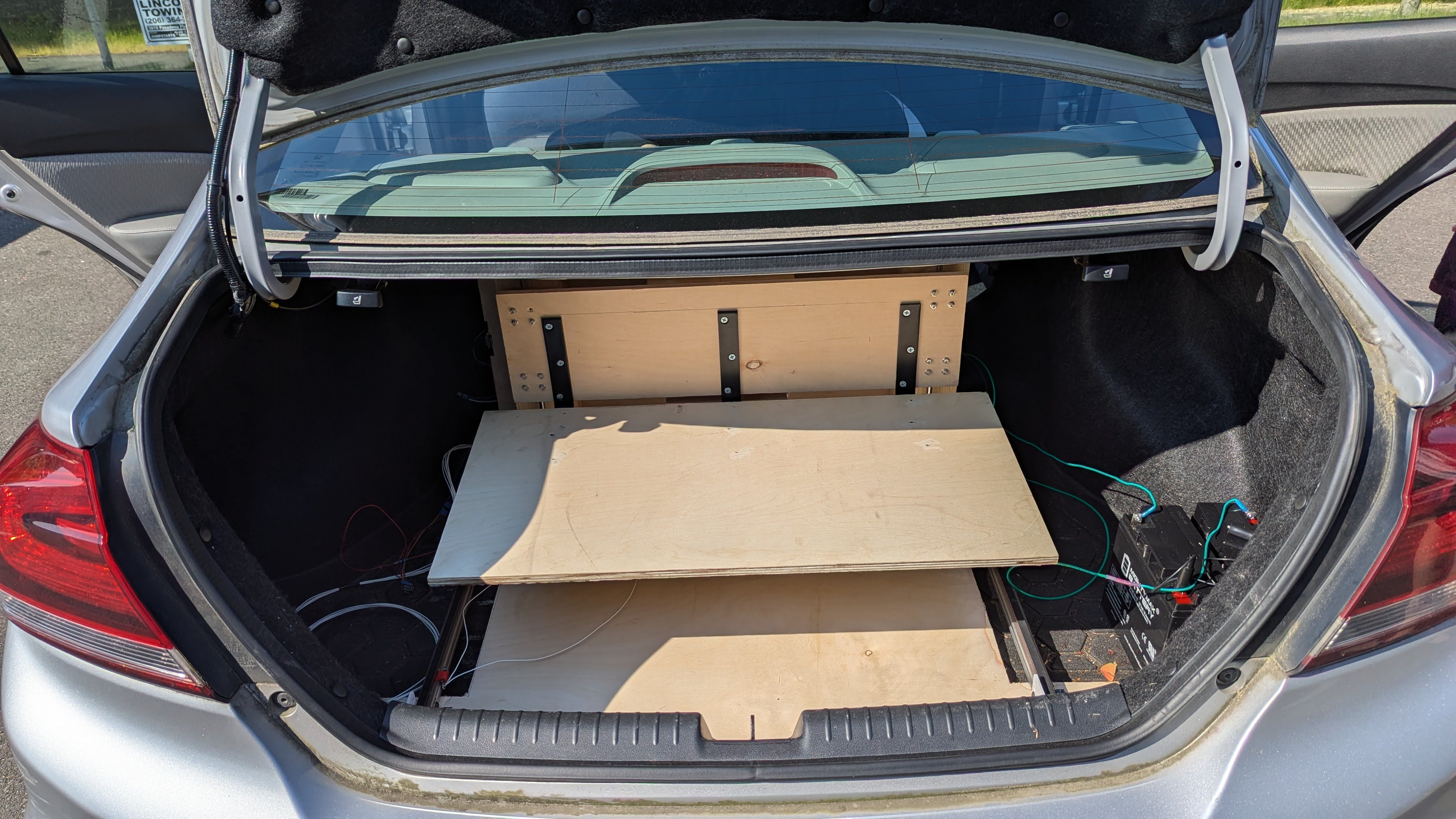
Final lifiting mechanism in a Honda Civic Trunk

Project Overview

For the disabled and mobility challenged, loading and unloading automobiles are a challenge. Most commercial car loading solutions are meant for larger vehicles vehicles like trucks and vans. The goal of "Gettin' Loaded" was to create a low cost trunk loading and unloading system for sedans. A system of lead screws, linear guides, and stepper motors were used for creating a strong, reliable, and safe product for the end user.
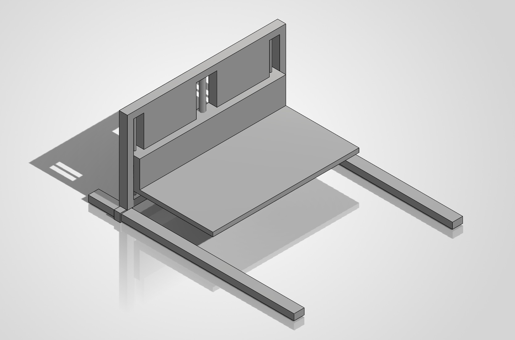
Rough Mockup of Loading Mechanism
Priliminary design and mockup in SolidWorks

Design and Construction

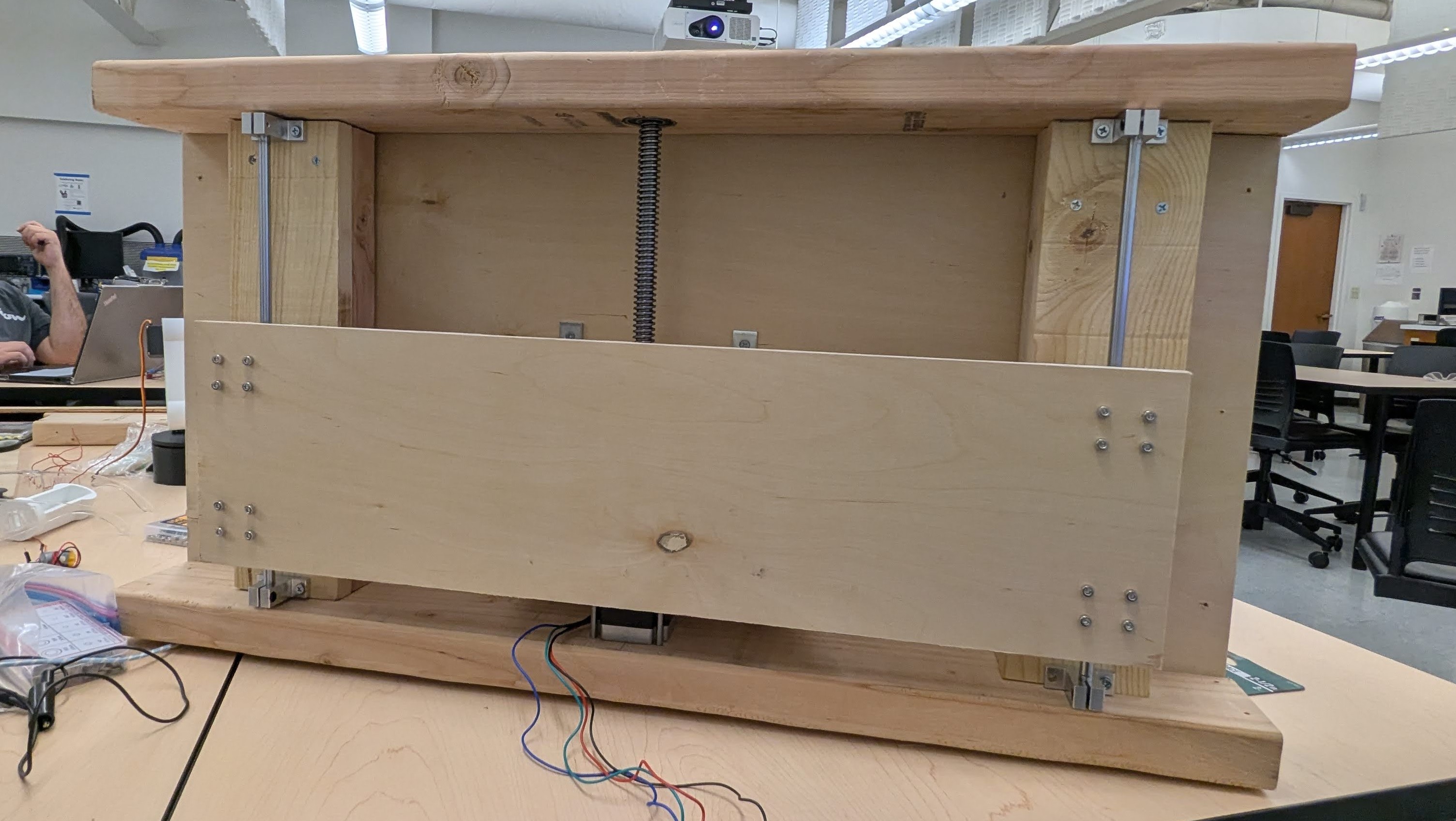
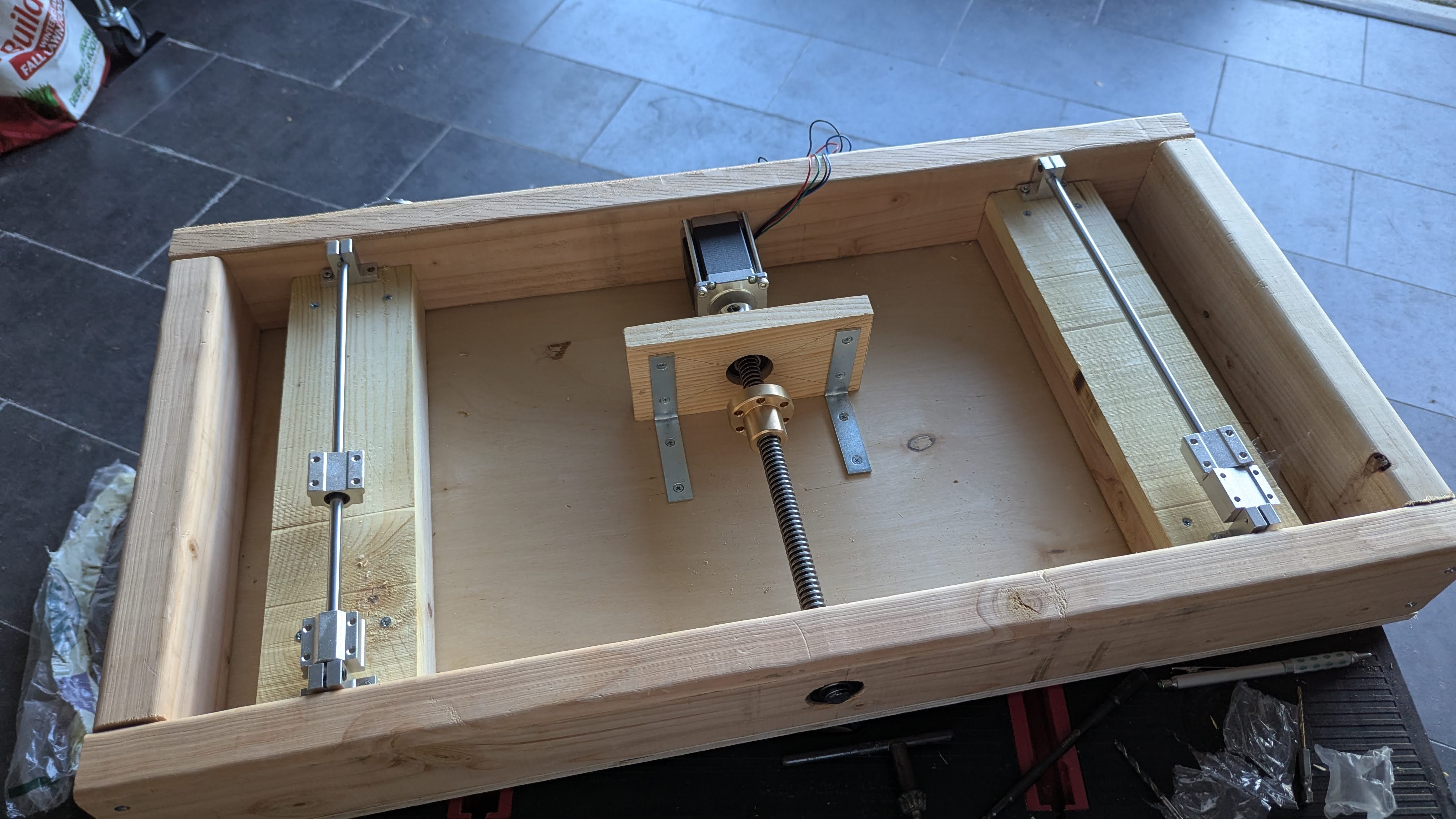
The system utilizes a forklift-like design. A backboard containing the lifting mechanism and its components are moved by stepper motors and belts on extruded aluminum rails. The backboard uses a system of linear guides, a stepper motor, a lead screw, and a lead nut to provide lifting power. Stepper motors were chosen for their strength, accuracy, and safety due to natural holding torque even when the system is off. The main construction of the backboard is made out of wood for a lightweight yet strong construction.
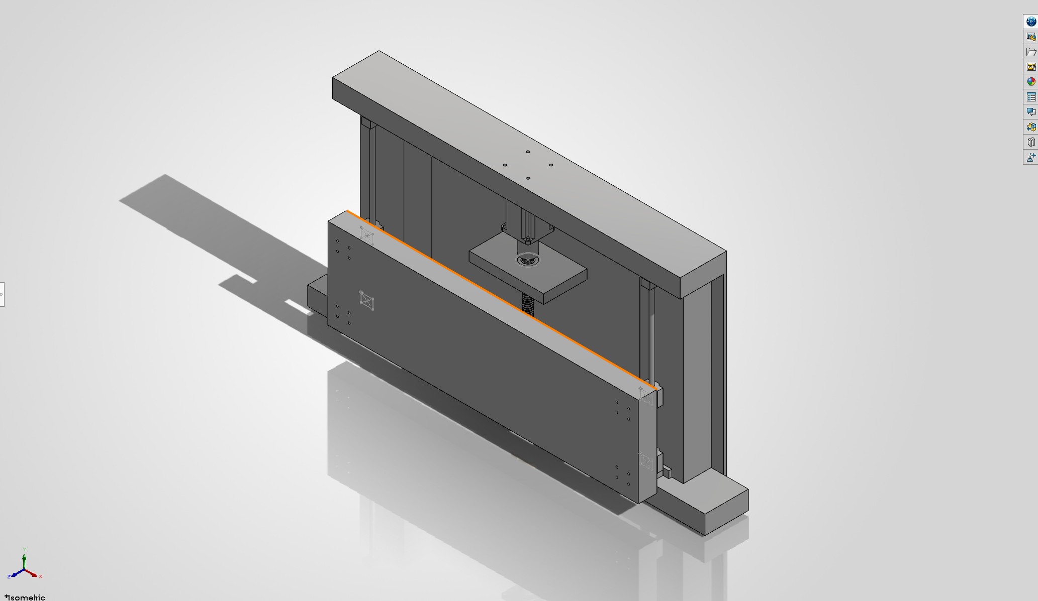
Solidworks Design of the Lifting Mechanism
Solidworks Design of the lifting mechanism proper
Built Backboard of the Lifting mechanism
Built backboard showing the motor, lead screw, linear rails, and bearing mounting.
Built Backboard of the Lifting mechanism
Built backboard with lifting backboard

Leveraging 3D Printing

The mechanism was designed in a way for easy adjustment on the fly when constructing the backboard. The pieces of wood which contain the linear rails you see above were free moving parts until the final position is settled. In the same way, 3D prints were used to ease overall construction. 3D printed spacers between the linear bearings and the lift were used to provide just enough room between stationary and moving parts for compactness. Custom 3D printed mounts for safety switches were designed and used for on the fly adjustment of start and stop points. Stencils were printed as a way to easily mark where drill holes were needed without excessive measurement.
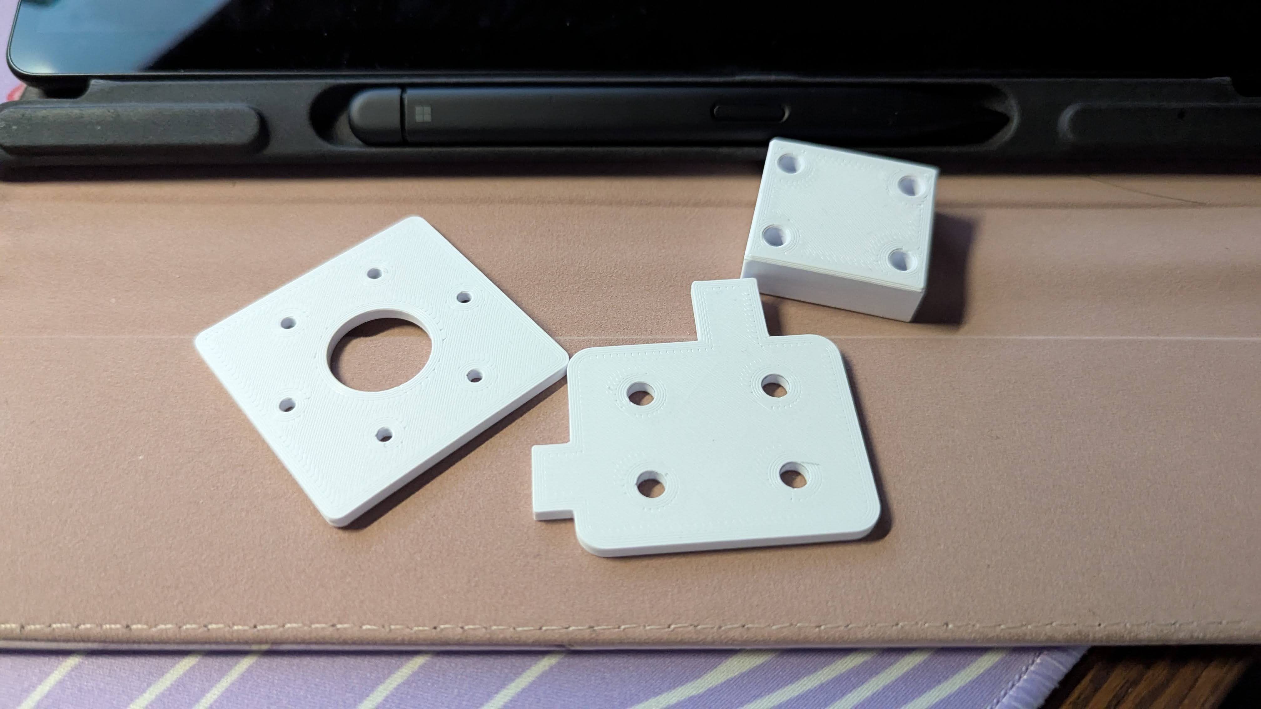
Stencils and spacers printed out for construction
Two stencils (left) and the linear bearing spacer (top right)

Video Editing

I edited my group's final presentation video. I used Davinci Resolve, combining powerpoint slides, audio from team members, and added my own professional voiceover with a Shure SM58.

Project Video Demonstration and Presentation

  • Back to Portfolio

About Me

I'm Thaddeus, I also go by Thad or Ted. I am a recent Mechanical Engineering Graduate from Seattle Pacific University. Currently I am looking for Mechanical Engineering jobs or internships in control systems design, sustainable engineering, or robotics. At the moment I am studying on my own time for the FE exam to obtain my EIT certification, while my long term goal is to complete a master's degree in Mechatronics, Electrical Engineering, or Computer Engineering. I have a wide range of interests and experiences, from Architecture and Interior Design, to Home Labbing and 3D Printing. Feel free to contact me!

Connect with me!

  • Location

    Seattle, WA

  • Email

    thadhowork@gmail.com

  • LinkedIn

    www.linkedin.com/in/thadzzho/

  • Phone

    (425) 209-8093

  • © Creative Commons.
  • Design: HTML5 UP: Dopetrope