Kite Control Unit: Mechatronics & Fluid Mechanics
Control Theory and Mechatronics in Alternative Sustainable Energy
Project Overview
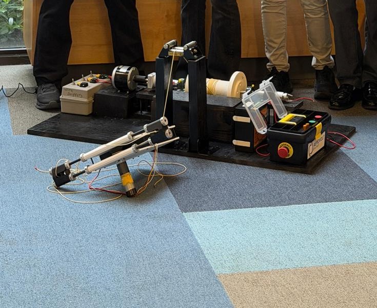
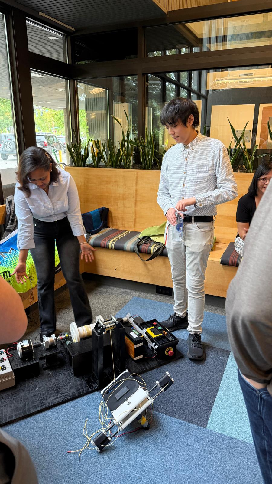
Airborne Wind Energy (AWE) is a category of sustainable energy generation that involves harnessing stronger and consistent winds at high altitudes. The category is a relatively new and experimental form of renewable energy dating back to the 1980s. This project was part of a senior capstone project as part of Team AeroVolt to create the Ventus One: a prototype nanogrid-scale AWE Crosswind Kite Power System (CWKPS) as the foundation for further research and development for future undergraduate senior engineering capstone project teams. CWKPS involves two sections: the Ground Control Unit (GCU), and the Kite Control Unit (KCU). The KCU is a mechatronics controller that flies a soft body kite sail while suspended in the air to create tension in a connected tether which spins a spool at the GCU. The GCU is a ground electrical station where energy is generated from the tether tension and is responsible for reeling the kite and KCU inwards as part of a generation and reel-in cycle. I worked with a electrical engineering classmate to design and fabricate the KCU, develop basic and advanced control loops for basic filght functionality, and conduct field test flights of our kite.
MATLAB Modeling
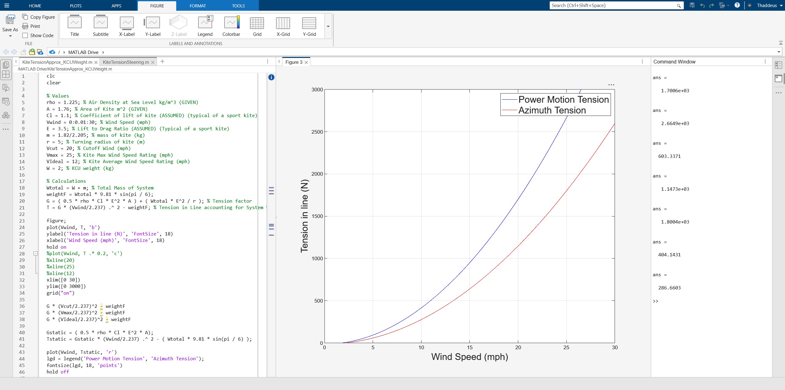
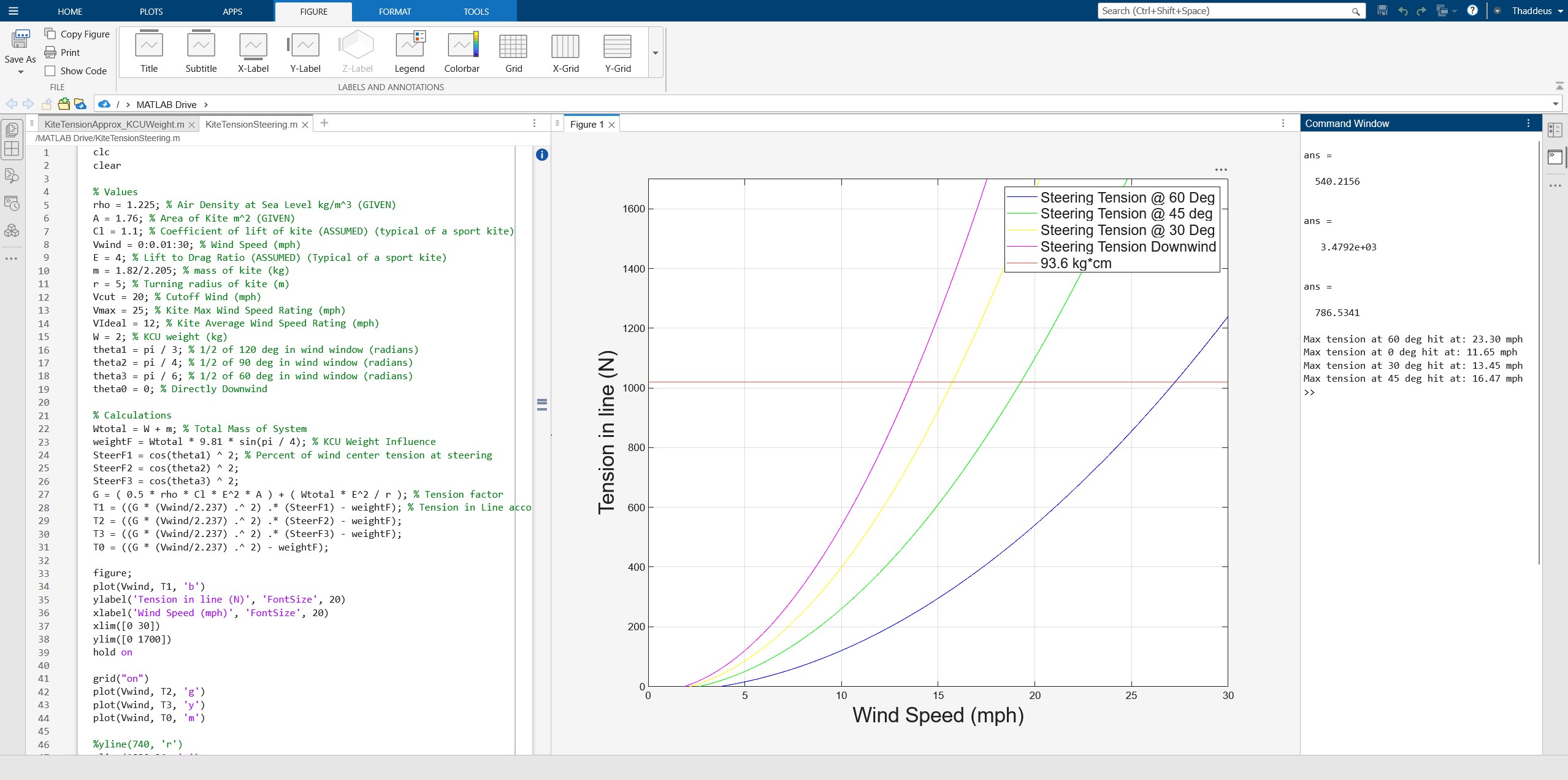
In order to size and determine the torque needed to steer the kite with the KCU, modeling of the aerodynamic and inertial forces of the kite were needed. The tensions created by a sport foil in a figure eight pattern is significantly higher than a kite stationary in the air. This figure eight pattern is the primary means of creating high tension for power generation, also called power steering the kite. A simple MATLAB model of the azimuth and power steering tensions first allowed us to estimate what strength of tether was needed to connect the KCU to the GCU. A second model of the steering torque and forces needed at various angles with the power motion gave us variou ranges of steering viability with a selected steering motor at different wind speeds. This information helped with choosing and verifying through theory that a chosen motor would be able to steer our two meter squared sport foil.
Design, Construction, and Iterative Improvements
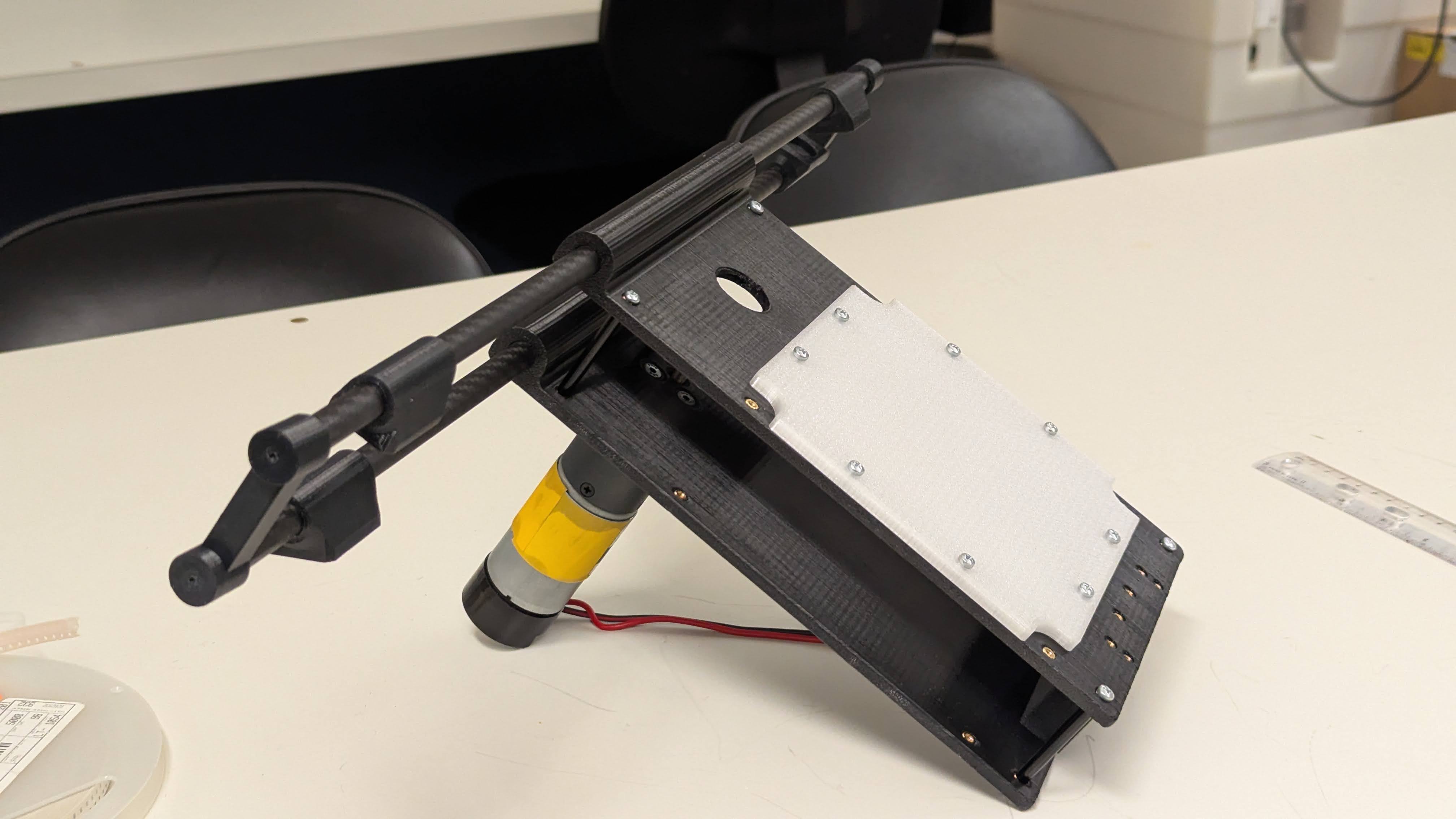
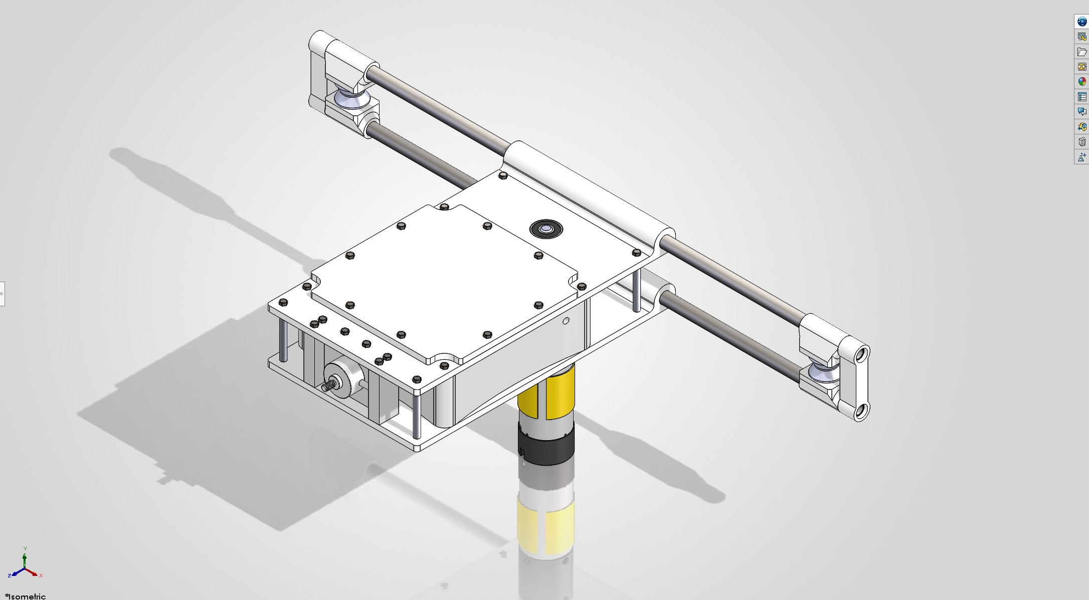
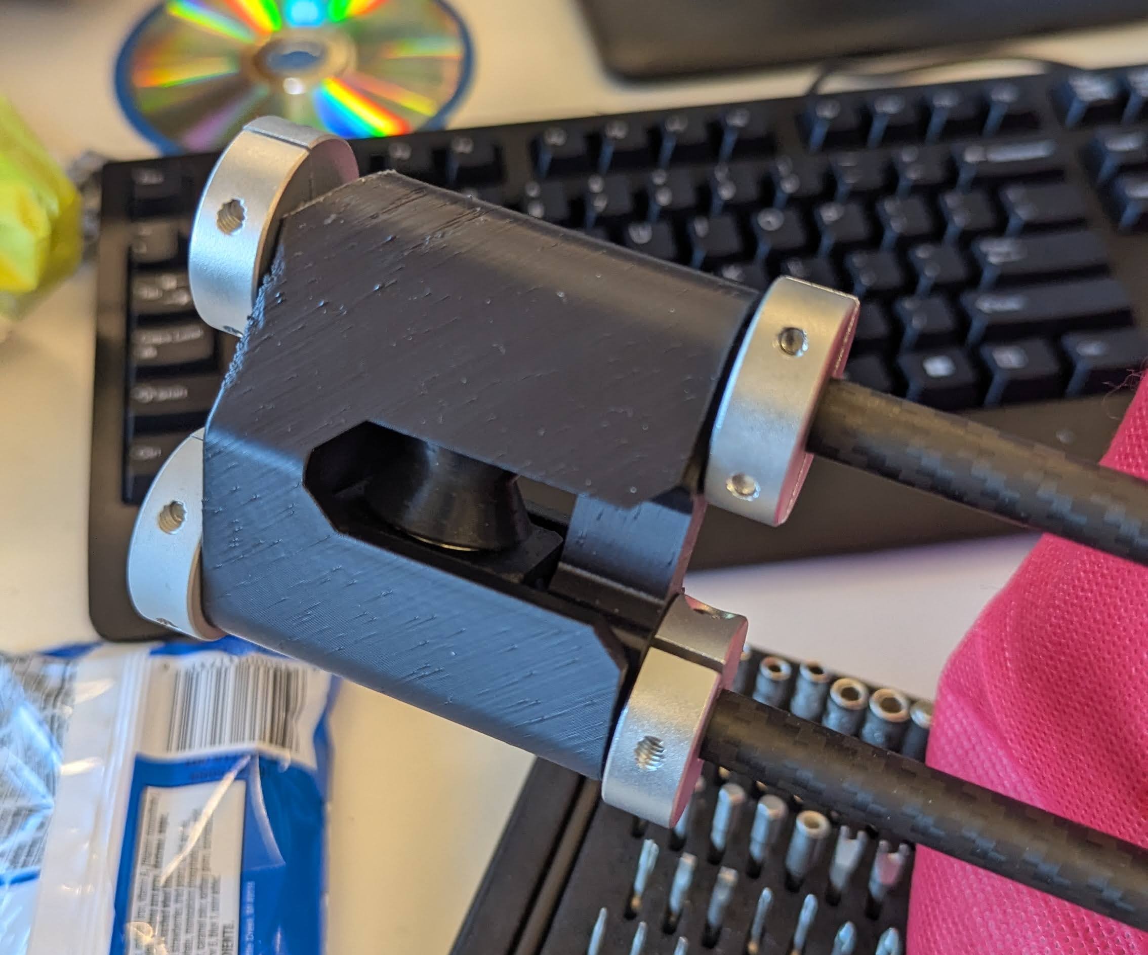
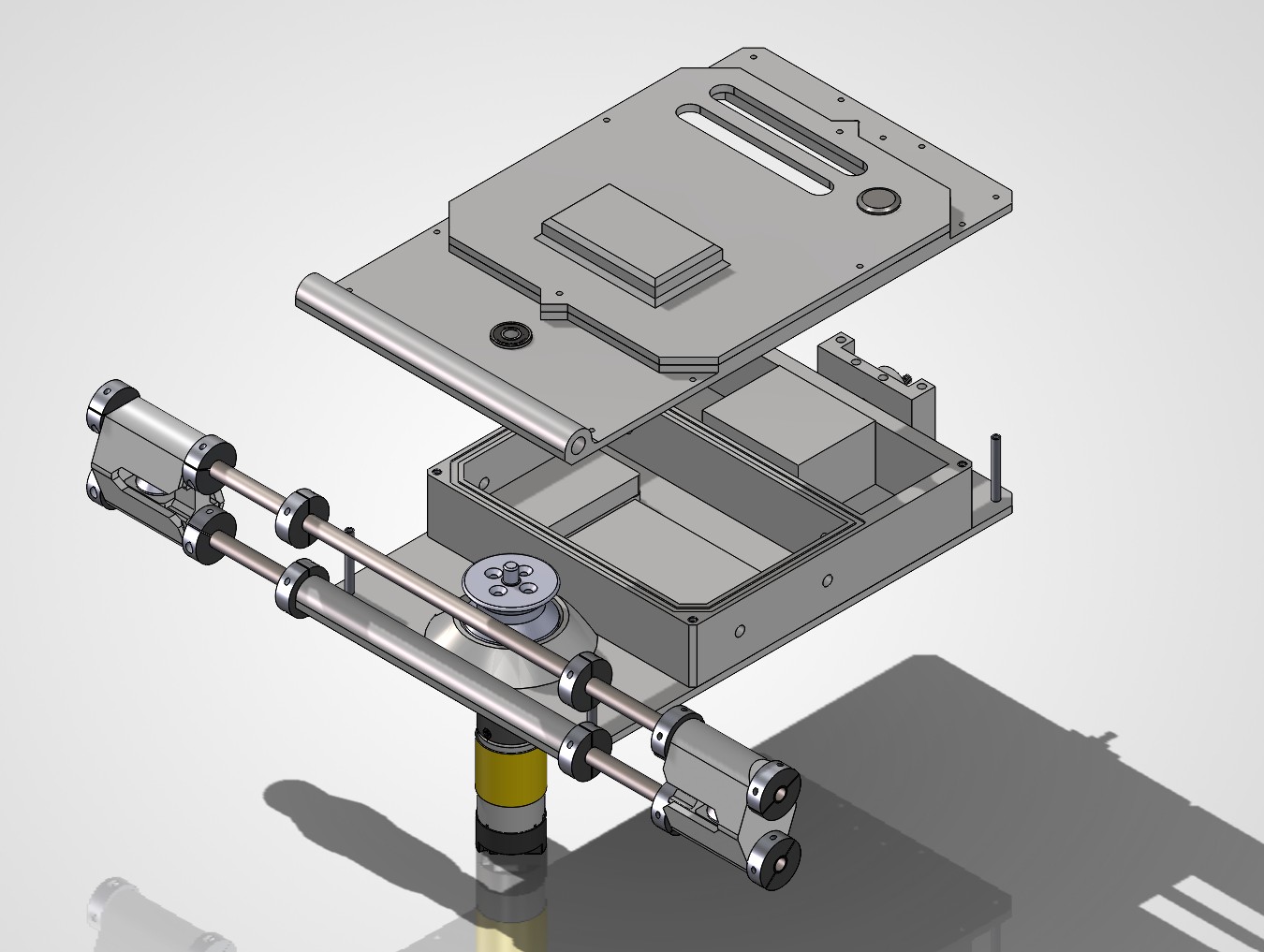
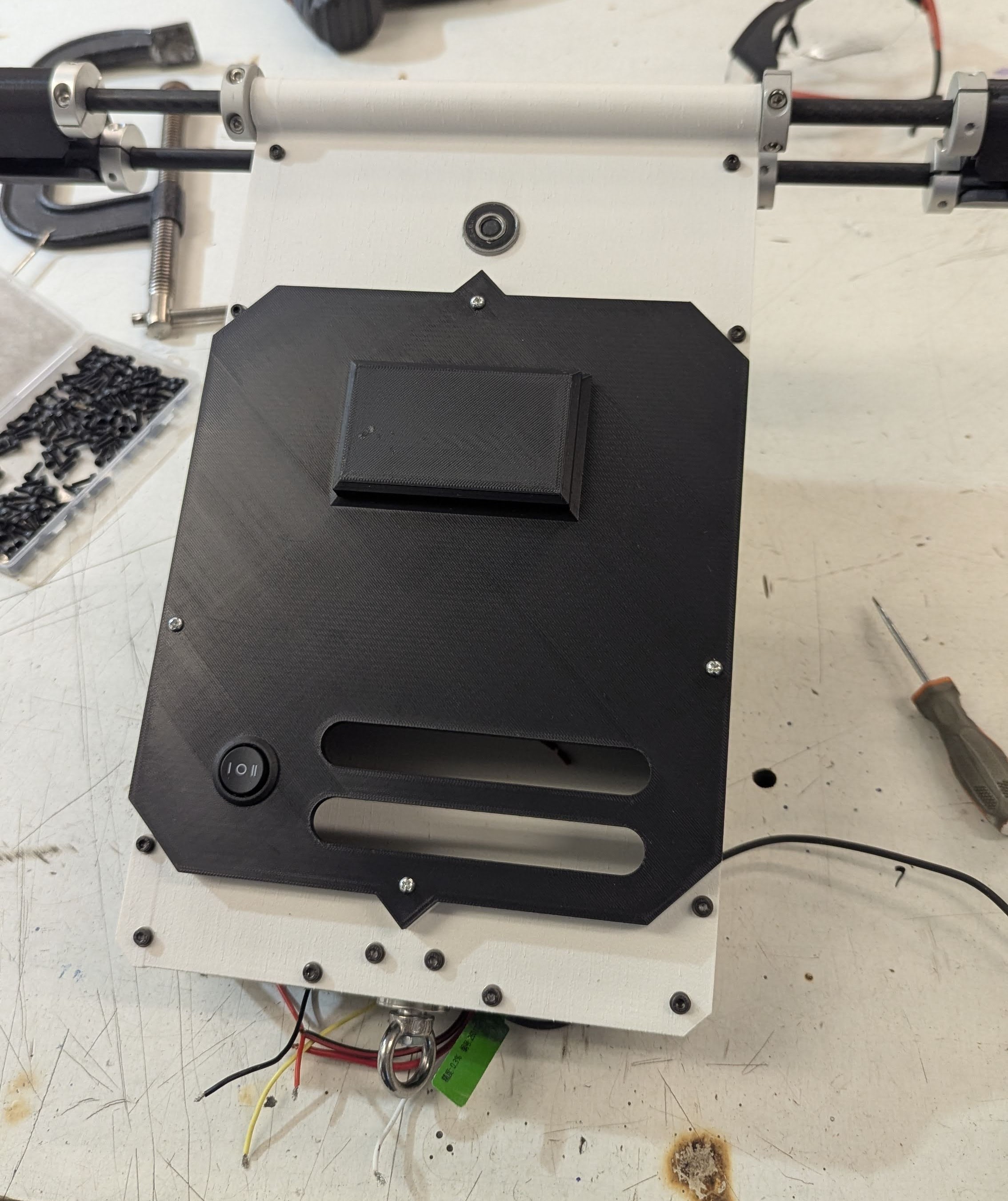
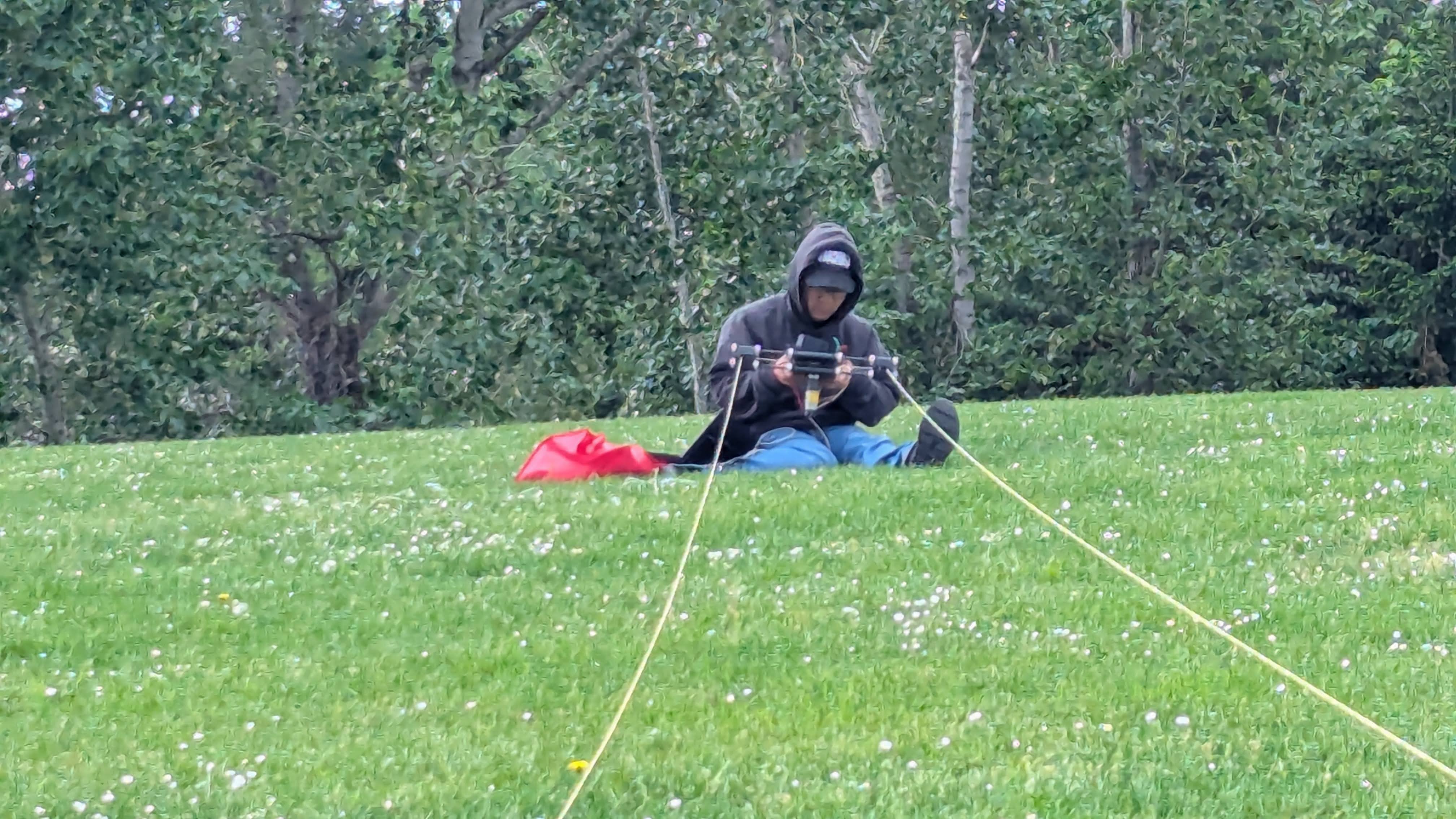
While commercial designs of a KCU are in the works by large research groups for microgrid systems, our prototype is for scholarly research and nanogrid-scale energy generation. As such our design is contrained by the tools, components, and materials of our given budget of 1500 USD, of which 500 was reserved for the KCU. This design utilizes 3D printed sandwiched plates body housing the electronics, main steering spool, and tension load cell. These plates connect to a pair of carbon fiber tube arms which hold guide spools to route the steering line connected to the kite. The purpose of this control bar like design to steering was attempting to eliminate the cost and complexity of a separate MCU wireless unit on the kite for sensing roll and speed, which commercial CWKPS have. Our goal was to have all the airborne electronics within our KCU, and as such the control design was to roll the KCU with the kite while all motion sensors sit within the KCU. The steering motor hangs off one of the sandwich plates.
A vast majority of parts were 3D printed if they weren't commercially available like the motor, load cell, and required hardware for construction. This was done for the purpose of rapid fabrication of both improments and prototypes. All custom designed parts were printed out of ASA or ASA-GF, an ABS alternative and that same ABS alternative with glass fiber reinforcement respectively, in order to have the KCU be highly resistant to weather. ASA swaps the butadiene rubber for acrylate rubber for improved resistant to moisture, water, and UV rays.
Controller Design
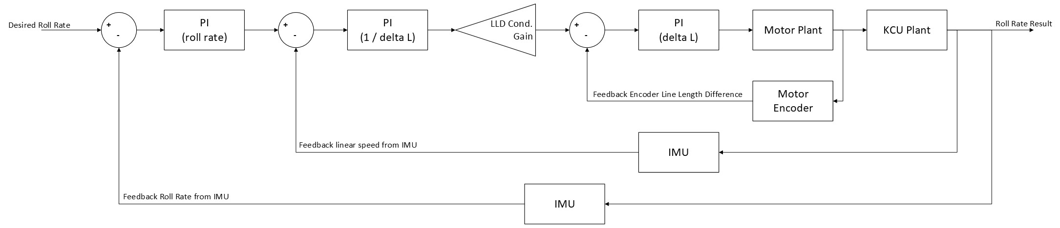
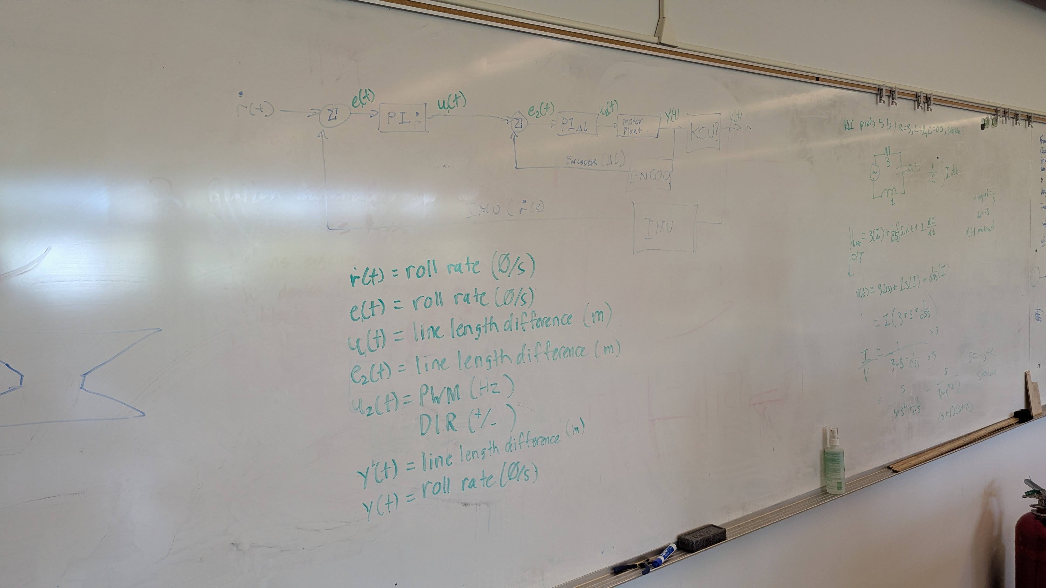
As part of the small two person team working on the KCU, I collaborated with the KCU electrical engineer to design and refine a controller for the KCU's control loop. We were advised by a professor specialized in mechatronics and control systems theory. We started with a double nested loop design after a preliminary field test, then refined the design to a triple nested loop to take advantage of three separate feedback and measurement loops. The order of the nesting from our IMU to the encoder was important for the loops to self correct errors through expected and unexpected disturbances.
Field Testing Validation
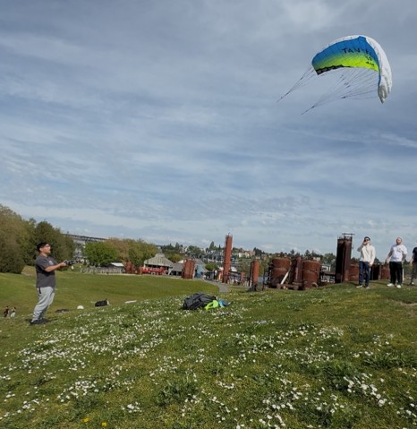
Many field tests were conducted throughout the 9 month time frame of the project. At the beginning, many flights of just the kite itself with simulated loads were conducted by the KCU team (including myself) to gather an intuitive understanding of kite steering. Much legwork was conducted to test suitable windy testing sites around the Puget Sound. The sites chosen and where flight testing took place were Chambers Creek Regional Park in Tacoma, Gasworks Park and Magnussen Park in Seattle, Marymoor Park in Redmond, and Fort Casey State Park. First tests of the KCU prototype were conducted at short range, and subsequent tests for steering happened with long steering lines.
Project Video Demonstration
Additional Photos